Preface
I recently had the opportunity to work on an integration between the Contiki OS and the ns-3 network simulator. I found that documentation was sparse on the Contiki side and ended up having to dig through the source code to understand its operation. The following post encompasses my findings which were also submitted as a degree requirement for the MEng. Computer Networks program at Ryerson University.Please excuse any out of context references as this was pulled from a paper that was not solely focused on Contiki.
Contiki OS Scheduler
The Contiki Operating System came to existence as an
extension of the uIP network stack, which was developed out of the Swedish
Institute of Computer Science. Its
design allows for features such as multi-tasking, multiple threaded processes,
remote GUI and a fully functioning customizable network stack – the RIME stack
– along with the original uIP stack [3].
Being extremely lightweight, the operating system only requires around
100 KB of memory for core operations, which makes it suitable for memory-constrained
devices such as microcontrollers.
Applications for Contiki include streetlights, home and factory
automation devices, security devices and various industry-specific monitoring
devices.
Looking under the hood, the remainder of this section examines
the scheduler at the core of the Contiki OS.
The following graphic displays the flow of control within the kernel.
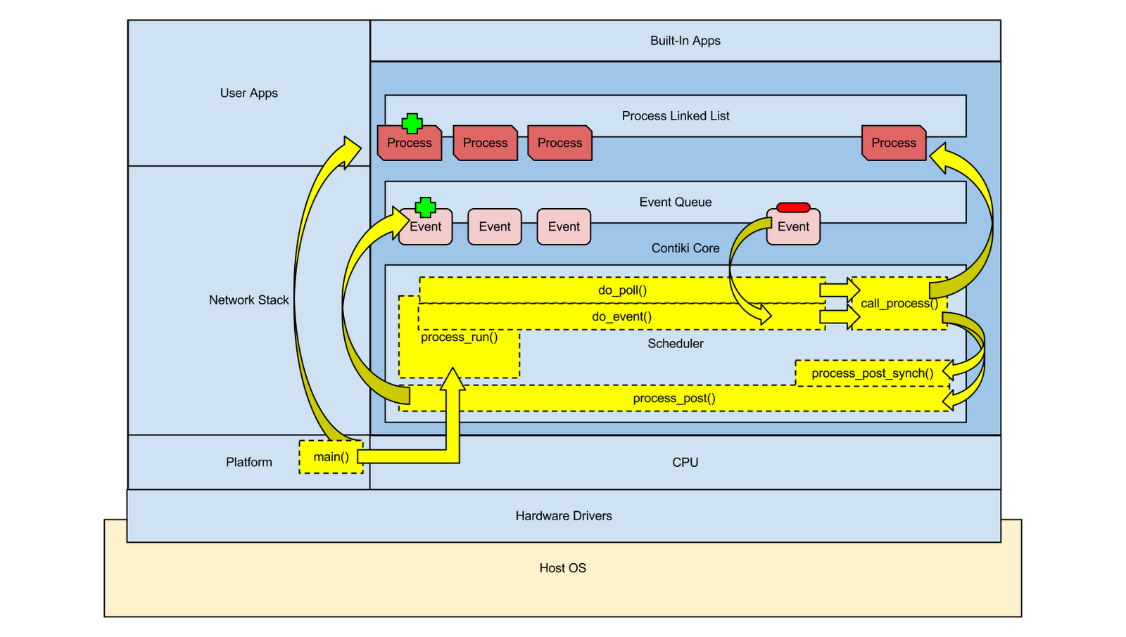
Looking at the figure above, all processing begins with the main() function within the
Platform code visually depicted on the bottom left of the diagram. The main() function,
usually defined within the platform-specific code (i.e. contiki/platform/ns3) starts
a set of concurrent processes using the PROCINIT macro:
PROCINIT(&etimer_process, &tapdev_process, &tcpip_process, &serial_line_process);
PROCINIT(&etimer_process, &tapdev_process, &tcpip_process, &serial_line_process);
The set of listed processes can be user applications, device
drivers, network stacks or other optional core functionality depending on the
overall function of the Contiki node. For example, the minimal-net platform
requires a tap device connecting into the underlying host OS and therefore
defines the &tapdev_process in its set
of processes to start. Once all
processes are started, control shifts to the scheduler. The driving function, process_run(), is usually called within a while loop
from the main() function.
process_run() then schedules
a series of functions that do the following:
- Checks a poll flag typically set by device driver processes, event timer processes, and any process utilizing IPC. If set, the process' poll handler function (the function defined to respond to the PROCESS_EVENT_POLL event) will be called immediately.
- Adds events to the event queue.
- Removes events from the event queue.
- Processes the functionality of the removed events by giving control to the process specified in the event which resides in the process list.
The default scheduling algorithm pulls events from the front
of the queue while ensuring that polling is done in between processing events. An event can either schedule subsequent events
at the back of the event queue via the process_post() function or can
immediately call a process to skip queuing with the process_post_synch() function. Polling results in a device, event timer,
or IPC-enabled process immediately running its poll handler function which can
make use of the process_post() and process_post_synch() functions to
schedule further events or run other functions.
When data from the application layer is generated, an event is scheduled to
invoke the configured NET/MAC stack so that it can read from the application
layer. When the event reaches the front
of the event queue, the network stack will operate on the layer 7
data in memory and then pass its pointer down further to the configured hardware
driver by scheduling either targeted events (i.e. TCP_POLL used to indicate
data is ready for the network layer from the transport layer) or general events
(i.e. PROCESS_EVENT_POLL). When this
event is at the front of the event queue the correct process can be called using
an event addressing mechanism that ensures that the correct member function can
be called based on the selected event name.
Data on its way in from the hardware relies on poll flags to
interrupt sequential event queue processing. When data arrives, it is written to memory and
the receiving device driver process sets a poll flag. Between subsequent events, the poll flag
belonging to each process is checked. If
a flag is found to be set, the process' poll handler function is invoked which
is defined by the PROCESS_POLLHANDLER macro. Therefore, in between subsequent scheduled
events there is always an opportunity for some network I/O to occur. A device driver can include both input and
output in its poll handler.
For example, data can originate from the application layer
and be written to the single memory buffer reserved for network I/O. An event can be scheduled at the back of the
event queue to send this data out via the hardware. Before this event reaches the front of the
queue, incoming data from the hardware can signal the device driver to set the
poll flag concurrent to event queue processing. After the next event is processed, the poll
flag is checked for all processes revealing that the network device has some
work to do. The poll handler function is
called that writes the data that has been prepared by the APP/NET/MAC layers before the scheduled event for this
write action has reached the front of the event queue. Additionally, the poll handler reads the
incoming data from the hardware buffer into the newly freed data buffer for the
APP/NET/MAC layers to operate on in the upwards network stack direction. The poll handler finishes and control is given
back to event queue processing.

Contiki OS Network Stack Architecture
Choosing a MAC protocol is performed by mapping function
pointers to appropriate functions. The
network stack is defined in the platform/…/contiki-conf.h
configuration header file, which takes a modular approach to the network layer,
radio duty cycle, MAC layer, radio driver, and framing. Each configurable element of the network
stack is represented by a structure as shown in the code snippet below:
extern const struct network_driver
NETSTACK_NETWORK;
extern const struct rdc_driver NETSTACK_RDC;
extern const struct mac_driver NETSTACK_MAC;
extern const struct radio_driver NETSTACK_RADIO;
extern const struct framer NETSTACK_FRAMER;
extern const struct rdc_driver NETSTACK_RDC;
extern const struct mac_driver NETSTACK_MAC;
extern const struct radio_driver NETSTACK_RADIO;
extern const struct framer NETSTACK_FRAMER;
Each structure is originally defined in its own header file
where a list of required functions accompany the structure. For example, in core/net/mac/mac.h there are six
function pointers defined.
struct mac_driver {
char *name;
/** Initialize the MAC driver */
void (* init)(void);
/** Send a packet from the Rime buffer */
void (* send)(mac_callback_t sent_callback, void *ptr);
/** Callback for getting notified of incoming packet. */
void (* input)(void);
/** Turn the MAC layer on. */
int (* on)(void);
/** Turn the MAC layer off. */
int (* off)(int keep_radio_on);
/** Returns the channel check interval, expressed in clock_time_t ticks. */
unsigned short (* channel_check_interval)(void);
};
Any MAC protocol chosen for compilation into the Contiki
executable must provide the required functions and also modify the struct
defined in netstack.h to apply the
function pointers to the defined functions. An example of this is shown below
pulled from core/net/mac/csma.c:
const struct mac_driver csma_driver = {
"CSMA",
init,
send_packet,
input_packet,
on,
off,
channel_check_interval,
};
"CSMA",
init,
send_packet,
input_packet,
on,
off,
channel_check_interval,
};

The diagram above displays the flow of control within the Contiki OS
during network input. Data originates
packaged with all layer headers via the hardware driver process. In this case, the socketradio.c/h files specify how to pull information from the
underlying OS IPC socket. The raw data is copied from the socket to the packetbuf memory
buffer, which is typically reserved for MAC layer processing of data. The faint
green arrow displays this movement of data from the socket to the memory
buffer. Control then shifts from the
device driver process into the OS network stack. The network stack is a series of preconfigured
(during compilation) function calls that chain into each other up and down the
stack. For sicslowpan/sicslowmac, the network stack is composed of the sicslowpan driver (network layer), the nullmac driver (MAC layer), the sicslowmac driver (Radio Duty Cycle),
the framer802154 driver (Framer), and
a variable radio driver that was chosen to be the socketradio device driver in this case to socket communication with
ns-3.
From the device driver, control moves up the stack starting
at the radio duty cycle component as shown by the yellow arrow leading out of
the device driver process. The RDC
invokes the framer whose responsibility is to parse the contents of
the packetbuf buffer and assign values to globally accessible
structural variables that indicate packet information such as header lengths. Once packet inspection is complete, the framer
returns control to the RDC, which then invokes the assigned radio duty cycle
driver - sicslowmac. Processing at this stage is focused on
stripping the layer 2 header from the contents of the packetbuf buffer
since all pertinent information has been recorded into separate variables by
the framer. The sicslowmac driver then calls up the stack to the configured nullmac driver. Here, no operations occur involving any memory
buffers. Control then forwards onto the network layer. The sicslowpan
driver is called via the network stack whose main responsibility in the upward
stack direction is header decompression. The sicslowpan
driver reads the packetbuf buffer and
compressed fields are decompressed into the sicslowpan_buf buffer.
Once decompression of the compressed
header is complete, the payload is copied from the packetbuf buffer
to the correct address following the uncompressed layer 3 header in the sicslowpan_buf buffer.
Finally, once the full packet is
assembled, it is copied from the sicslowpan_buf buffer to
the uip_buf buffer.
Control is then forwarded to the tcpip_process using
a process_post_sych. This
schedules an event that is immediately processed and the tcpip_process is
signaled with the TCP_POLL event. Further
layer 4 and subsequent layer 7 processing continues after the delivery of the
data from the network stack to the expected uip_buf buffer.
Sending data follows a similar flow of control but in the
reverse direction. The application layer
data is written to the payload of the uip_buf buffer and the layer
3 headers are filled in as well. Passing
control down the stack to the sicslowpan
driver, compression of the layer 3 header is performed by reading the header
within the uip_buf buffer and writing the compressed version
to the packetbuf buffer. The payload is also copied over by the sicslowpan driver. The nullmac
driver forwards onto the sicslowmac
driver which adds 802.15.4 framing before forwarding to the configured radio in
the network stack for network output. Sending
layer 4-initiated data (i.e. TCP ACKs) occurs automatically on receipt of data
and the application is never notified of this. In this case, the registered sicslowpan output function is triggered
by the tcpip_process to initiate data passing down the stack
to the radio.
Contiki OS Sensor Architecture
The simulation environment operates with purely virtual
components. There are virtual nodes
talking over a virtual medium using virtual sensors to gauge their electronic
environment. For the purpose of writing
a suitable application to test the integration, the simulated wireless sensor
node required some form of real world sensing however. Therefore, a sensor was built that monitors
the input to a host OS socket for specific values controlled by an external
user-controlled frontend. Contiki
implements a blanket sensor process that acts as a platform for all hardware
sensors attached to the node. Sensor
hardware drivers were written to the interface specifications of the main
sensor process so that this process could launch and schedule sensing
operations as shown in the following diagram.

Sensing typically begins with the sensor specific processes
shown on the right of Figure 8. These
processes are launched on Contiki startup and bind to/initialize any hardware
they are designed for. For example, acc-example.c defines a process specific
to monitoring an accelerometer by polling its x-y-z co-ordinates every half
second. If something noteworthy occurs,
the sensors_changed() function
can be invoked to schedule an event that will signal the sensors_process that
there is further work to do. This is
shown on the right in the diagram above as new events are added to the event
queue originating from the sensor specific processes.
Once the event generated by the sensors_changed() function
reaches the front of the event queue, the scheduler passes control over to
the sensors_process process whose purpose is to check all
attached sensors and notify interested processes of any changes. The two arrows leading from the event queue to
the Sensor Scheduling Process via the Scheduler in the diagram above display
this logic.
The Sensor Scheduling Process (also known as sensors_process)
found in core/net/lib/sensors.c and sensors.h maintains
two arrays: an array of pointers to sensors (the specific sensors corresponding
to sensor drivers) and an array of flags each of which corresponds to the
attached sensors. For example, if a node
had a temperature sensor, a vibration sensor, and an accelerometer as attached
hardware, then there would need to be three separate device drivers used to
register these components to the sensors_process. The sensors_process would
maintain an array of each sensor (3 in total) and an array of flags for each
sensor (3 in total). Upon receiving an
event, the Sensor Scheduling Process iterates through all sensor flags to see
which sensor has data that should be handled. The sensors_changed() function
that was mentioned earlier manipulates the array of flags maintained by the
Sensor Scheduling Process. The sensor
specific process tied to the hardware sensor that needs attention calls
the sensors_changed() function which manipulates the flag
corresponding to the specific sensor. For
example, a temperature sensor process would only manipulate the flag at the
index corresponding to its sensor in the array of flags via the sensors_changed() function.
The sensors_process checks all flags
iteratively. If it finds a flag set, an
event is scheduled to the event queue before checking any subsequent flags. The event that is scheduled is marked as a
broadcast event, meaning that when the main scheduler is processing it, the
main scheduler will push this event to all processes. This includes processes that do not care
about the event, processes that require the event to continue processing (i.e.
User Applications waiting for sensor input) and the sensor_process itself.
Notice the generation of the Broadcast Event,
which is placed at the end of the event queue via the Sensor Scheduling Process
in the diagram above.
This broadcast event will reach the front of the event queue
and will be delivered to an application process residing in the User Apps
domain (top-middle of the diagram). It
will also be delivered to the Sensor Scheduling Process, which will resume checking the rest of the
flags as processing was halted after scheduling the broadcast event that has
just been processed. This ensures that a
single sensor’s input is handled at a time.
The sensors_process will continue iterating
through the rest of the flags and acting upon them in the same manner described
above. If all flags have been parsed and
it is deemed that no sensors have generated noteworthy input, then the sensors_process will
sleep until another event wakes the process (i.e. a sensor specific process) to
check sensor flags once again.
No comments:
Post a Comment